Introduction
If you have spent any time around oil and gas plants, you have probably noticed that certain equipment just stays the same decade after decade. New technologies come in, processes get upgraded, and digital systems take over, but some things stay; shell-and-tube heat exchangers are one of those things.
You would think that with all the innovation in industrial heat transfer over the past 30 years, something would have come along to replace them. But walk into any refinery, gas processing facility, or offshore platform today, and there they are, long cylindrical vessels, bundles of tubes running through them, doing the same job they have always done.
That consistency is not stubbornness. It is proof that the design got something fundamentally right. This article explains why shell and tube heat exchangers remain the go-to choice in oil and gas, and what makes them suited to conditions that most other equipment simply cannot handle.
What Makes Oil and Gas Plants Different From Other Industries?
Before getting into why heat exchangers work so well here, it helps to understand what oil and gas plants actually demand from their equipment.
The conditions are genuinely extreme. You have:
- Fluids running at temperatures that can exceed 400°C
- Operating pressures that push well beyond what most industrial systems handle
- Corrosive media, crude oil, hydrogen sulphide, acidic condensate, flowing through pipes continuously
- 24-hour operations where equipment shutdowns cost serious money
Most heat exchange equipment handles some of these challenges well. Very few handle all of them together, consistently, over years of continuous operation. That is the standard oil and gas plants set, and shell and tube heat exchangers meet it.
How a Shell and Tube Heat Exchanger Works?
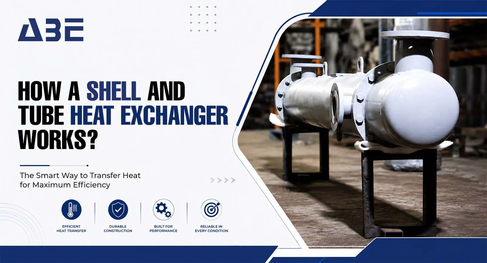
The basic principle is simple: one fluid runs through a bundle of tubes inside a cylindrical shell. A second fluid flows around those tubes, inside the shell. Heat transfers between the two fluids through the tube walls, without the two fluids ever mixing. No complex mechanisms, no moving parts in most configurations, no electronics that can fail mid-operation.
What makes this design so durable is exactly what makes it seem simple. Fewer components mean fewer things to break. And in an industry where an unplanned shutdown can cost hundreds of thousands of dollars per hour, that reliability is not just convenient, it is important.
Why the Tube Bundle Design Handles Extreme Conditions?
The tube bundle inside a shell and tube heat exchanger can be engineered in different configurations depending on what the process demands.
- Fixed tube sheet designs work well when both fluids are at similar temperatures
- Floating head designs allow the tube bundle to expand under high temperatures without stressing the shell
- U-tube configurations handle high-pressure differentials on the tube side
Oil and gas processes involve all of these conditions at different points in the plant. The ability to configure the same basic design for each condition is one of the main reasons engineers keep specifying heat exchangers; they are not locked into one solution.
Why They Outperform Other Heat Transfer Options in This Industry?
They Handle High Pressure
Plate heat exchangers, for example, are compact and efficient, but their gasketed design has pressure limitations. In oil and gas environments where operating pressures regularly exceed 30 bar, and sometimes go much higher, that limitation becomes a problem.
A properly designed shell and tube heat exchanger handles high pressure across both the shell side and the tube side. The cylindrical shell geometry distributes pressure load evenly, which is why these units are routinely used in high-pressure applications that other designs simply cannot accommodate safely.
Corrosive Fluids Are Not a Problem: If the Material Is Right
This is where the flexibility of heat exchangers shows. The tubes, tube sheets, and shell can all be manufactured from different materials depending on what is flowing through them.
- Carbon steel for general hydrocarbon service
- Stainless steel for acidic or mildly corrosive media
- Duplex stainless steel for chloride-containing environments
- Titanium for highly corrosive applications
Oil and gas plants deal with all of these fluid types at different points in the process. A shell and tube heat exchanger can be specified with the right material for each application rather than forcing one material to handle every condition.
Large Surface Areas Mean Better Heat Transfer at Scale
Oil and gas plants process enormous volumes of fluid. Achieving the heat transfer rates needed to cool, heat, or condense those volumes requires significant heat transfer surface area.
Shell-and-tube heat exchangers scale well. A single unit can contain hundreds of tubes, creating surface areas that run into hundreds of square metres. Larger units can be designed for exceptionally high flow rates without proportionally increasing the plant footprint. That scalability is something compact alternatives struggle to match.
What to Look For When Specifying a Shell and Tube Heat Exchanger for Oil and Gas?
Not every shell and tube heat exchanger is the same. If you are specifying one for an oil and gas application, a few things matter more than others.
Material of Construction
Match the material to your actual process fluid, not just the nominal operating temperature. Aggressive corrosion over the years of operation is one of the main failure modes. Getting the material selection right up front is significantly cheaper than replacing a unit after two years of service.
Tube Configuration and Baffle Design
The number of tubes, their diameter, and the baffle spacing inside the shell all affect heat transfer performance. A unit that looks correctly sized on paper can underperform if the baffle design does not create adequate turbulence on the shell side.
Maintenance Access
In oil and gas plants, maintenance downtime is expensive. A shell and tube heat exchanger with a floating head or removable tube bundle allows cleaning and inspection without taking the unit apart completely. For fouling services, crude oil cooling, for example, access is genuinely important.
Conclusion
Some equipment earns its place and stays there. The Shell and Tube Heat Exchanger has not stuck around because nobody thought of something better; it has stayed because nothing else handles high pressure, corrosive fluids, and continuous operation as reliably. That track record matters when you are specifying equipment for a plant that cannot afford surprises. ABE & HEX India Private Limited has spent over 15 years and 4,700 projects understanding exactly what that reliability requires.
FAQs

Abe & Hex India
Since 2009, ABE & HEX has been manufacturing premium quality heat exchangers. We fabricate high-grade products to meet different industrial requirements.
